Supposedly, Michelangelo was asked how he created David. He said it was easy. Just remove all the stone that doesn’t look like David.
While this is a frivolous take on the idea, building things is always a blend of adding and subtracting.
In the case of wood turning, it’s mostly removal. Take a cylinder of wood, spin it, and use some kind of sharp device to remove what you don’t want. The spinner is called a lathe. The device is called a turning tool.
I started wood turning a while back. I started with tiny lathes until finally I wanted to do some big things. This meant a big lathe. I looked around and found a used Delta lathe and bought it. This was a big thing: 14” inch diameter cylinders across a 42 inch bed. Better than 200 pounds of cast iron. I could take logs and peel them down to a workable size.
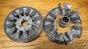
And after about a month, it broke. No, that’s not the pulley that broke this time. The first pulley to break was the motor pulley. The pulley shown is the spindle pulley.
Regardless, thus began the Saga of the Lathe.
A lathe is, essentially, four parts: the headstock, which actually turns the piece, the tail stock, which passively supports the piece against the headstock, the tool support you brace the turning tool that cuts the wood, and the bed that supports all of this. Nothing much goes wrong with the bed, tool support, or tail stock. But the headstock is another story.
The headstock is an astonishingly complex assembly. It’s a spinning hollow tube that allows placing all sorts of attachments in one end. This means it has a motor turning two pulleys: one end attached to the motor shaft (the motor pulley) and the other going inside the headstock to rotate that tube (the spindle pulley.)
We need to define a few terms here. RPM is revolutions-per-minute. This is how fast that hollow tube is turning and, by extension, how fast the wood being turned revolves. Torque is the rotational force coming from that rotation. Torque and RPM are completely separate qualities. There are high speed, low torque systems that you can stop with your hand. There are low speed, high torque systems that will tear your hand right off without slowing down. A 24 inch car wheel rotating at 10 rpm is, in effect, running at less than a mile/hour. But a human can’t stop it.
Most full sized lathes range between about 600 rpm and 2400 rpm using something like a 1700rpm, 1 horsepower motor. So, if you’re running the rpm of the lathe at the same natural speed of the motor, most of that horsepower is transmitted to turning wood. That’s a lot of torque.
Speed control is an important part of using a lathe. A twenty inch by twelve inch irregular log is barely manageable at 600 RPM (10 revolutions/second) and even then it’s scary as hell. Faster than that, it’s nightmare fuel. That said, turning a fine spindle at 2400 rpm is lovely and gets a beautiful, smooth surface.
There are several different mechanisms to change turning speed. The simplest, yet most expensive, is to use a DC motor and just put a controller in the circuit. DC motors will change speed relative to the power they receive. But this means you sacrifice torque—starve the motor of power and it certainly slows down but it gets weak, too. I’ve seen lathes turn at 60 rpm (1 revolution/second) that I could stop with my hand.
Most lathes, instead, use a constant speed AC motor and change the speed by changing the motor and spindle pulley ratios.
I love pulleys. They are human mechanical ingenuity its finest. Imagine two pulleys: one is, say, 2 inches in diameter. The other is 6 inches in diameter. Circumference is C = πD. So that 2 inch pulley is 6.28 inches around. The circumference of the 6 inch pulley is 18.9 inches. Connect the two with a belt so they must turn together. This means every time the 2 inch pulley turns three times, the 6 inch disk turns once. (More or less. Let's say that to avoid decimals.)
This is how lathes manage speed. They put the small pulley on the motor and the large pulley turns the lathe shaft. To change the speed, the ratio between the two pulleys is changed. Often, this is done by having a set of pulley pairs of different ratios and moving the belt from one ratio to another.
Changing the speed has an effect on torque as well. If the motor is running at a constant rate, when the effective pulley speed is the same rotational speed as the motor, the torque at the pulley is close to the torque on the motor. Let’s say the motor pulley is running faster than the spindle pulley (it’s the 2 inch in the previous example.) It’s already stated that the 2 inch pulley is turning 3 times faster than the 6 inch pulley. That means the motor has applied its horsepower to the motor pulley 3 times while the spindle pulley has turned once. Which also means the spindle pulley is getting three times the torque the motor pulley is supplying.
This is the way mechanical advantage (sometimes called leverage) works. It’s trading two related qualities across a conserved common quality. Think of a garden variety lever. What is being conserved is the angular rotation. Push down on one end of the lever and the other end goes up the same number of degrees. It doesn’t matter if one end is a mile long from the fulcrum and the other is an inch. Push down the long end of the lever ten degrees and the other end will rise ten degrees.
What is traded is the distance covered by the ends of the lever. If one end travels 10 inches and the other end travels 1 inch, 10 inches of force gets compressed to a 1 inch travel: a 10 to 1 mechanical advantage.
In the
case of this example of pulleys, the rpm is being traded but the linear distance
traveled at the pulley is constant. When the small pulley rotates 1 revolution,
two inches of rotational travel occurs. On the large pulley, two inches of
travel also occur. But the difference here is two inches is one rotation on the
small pully and 1/3 of a rotation on the large pulley. Thus, three times the torque in a single revolution.
But moving the belt is inconvenient. In addition, there’s a limit how many ratios can be put in the headstock. (Usually, it’s four.) What if we want much finer control? And we don’t want to sacrifice torque like the DC motor approach?
Enter the Reeves Pulley.
I was unable to find out who Reeves was, although I did see pictures of pulley systems with a Reeves logo on them. Presumably, there was a genius mechanical engineer a hundred years ago that came up with this. I hope he was well paid.

Look at the picture at left. (Picture from here.) Note that we are looking at two pulleys, each made up of a pair of flat cones. In this drawing, the upper pulley is movable but the speed measurement is against the bottom pulley. As the cones of the upper pulley are pulled close together, it increases the force against the lower pulley, forcing the two cones apart. The circumference of the lower pulley is now small while the upper pulley’s circumference is large. Let’s use the numbers we used before. Each time the 6 inch upper pulley turns, it rotates the 2 inch lower pully three times. If the upper pulley is turning at 100 rpm, the lower pully is turning at 300 rpm.
Now, if the upper pulley is pulled apart, a spring on the lower pulley pushes the cones together. Let’s say, we’ve now reversed the ratio. The lower pulley is now the six inch pulley while the upper pulley is the two inch pully. The upper pulley is still turning at 100 rpm. This makes the lower pulley turn at 33 rpm. (A good calculator is here.)
Variable transmission with minimum loss of torque.
What broke initially on the headstock was the motor pulley. I hadn’t done my homework. Delta had skimped on the materials used in the pulleys and used an inferior zinc alloy. The motor pulley had shattered.
I looked around and discovered that Delta had been out of business for some time and there were no parts available. However, a competing manufacturer made Reeves pulley pairs that sort of fit my motor. The problem was they were too small. Remember the pulley ratios? I could go slow but I couldn’t go fast. The original top speed was 2400 rpm. I was running at 1600.
Oh, well. I coped for the next couple of years.
I had been making tops for a while now and my son asked me to make him a big one. Okay, I said. I took a big piece of ash, hammered it into place. Made sure the alignment was right and turned on the lathe.
*THUNK* Hash. Rattle. Rattle.
Oh, crap, I thought. I opened the headstock and saw chunks and pieces of zinc alloy inside. See the picture above.
The spindle pulley had exploded. This was also the part of the Reeves system that actually moved under control, unlike the motor pulley that moved passively in response.
Now, I had a problem.
Sure enough, a search on line told me nothing about the Delta parts situation had improved. I went back to the surrogate supplier to get a new spindle pulley.

To the left here is an exploded view of the headstock. If you look at the part numbers, parts 5-8 is the motor pulley assembly. In the same drawing, parts 14-47 is the spindle pulley assembly.
I had my work cut out for me.


No comments:
Post a Comment